Fuel Pressure, Injector Duty Cycle and Maths Channels…
Most dyno users just go with the basic options of 1 AFR/Lambda input a Boost/Vac sensor on their Dyno’s, possibly due to that’s all that is available on some brands, or not realising the diagnostic potential of some additional inputs, or the value of some Maths Channels in Dyno Software.
To point out some of the valuable diagnostic help assistance some of these options can show, we will start with a pretty typical example of a car making 900+ Hp, with just AFR and Boost shown first:
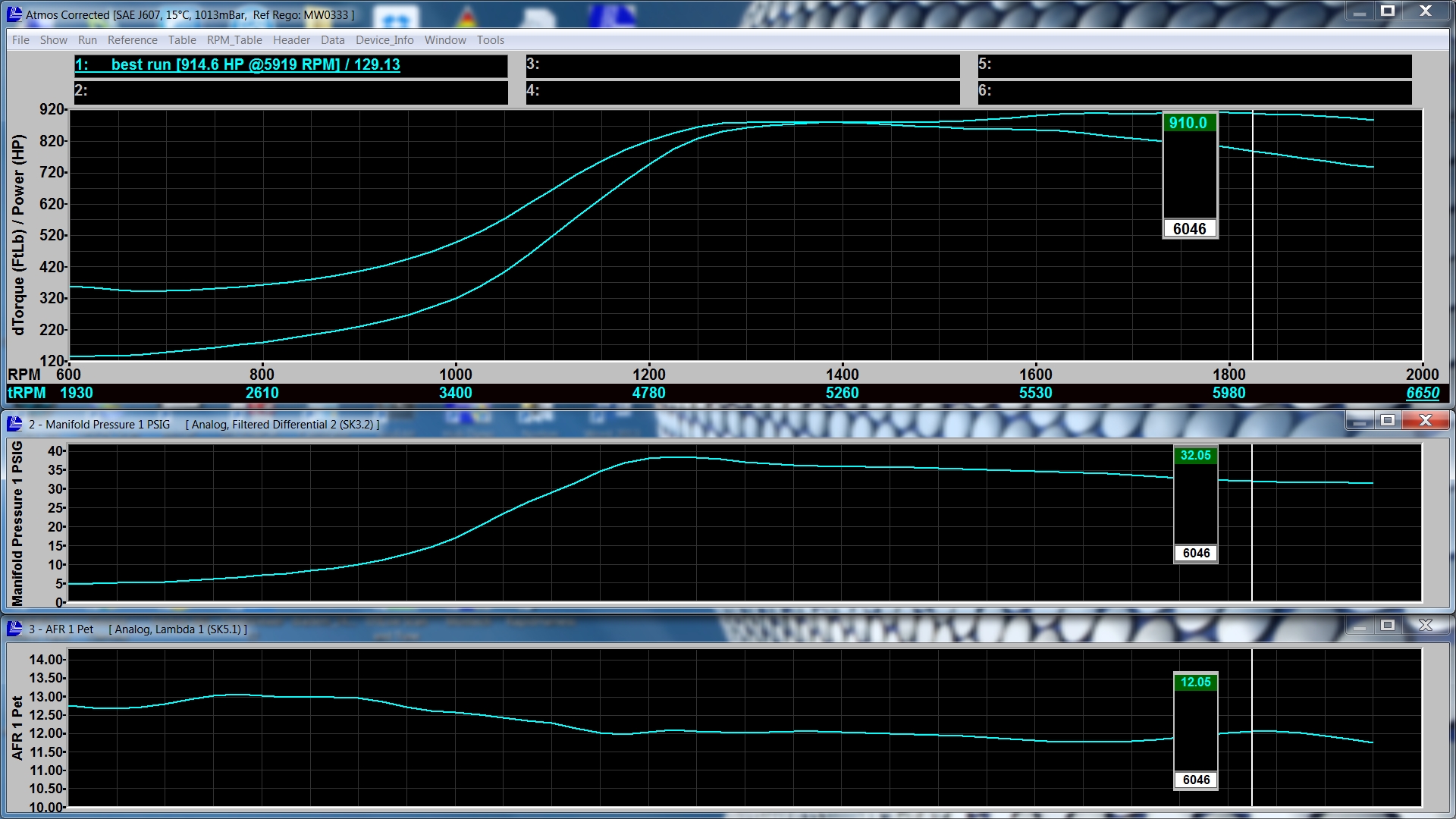
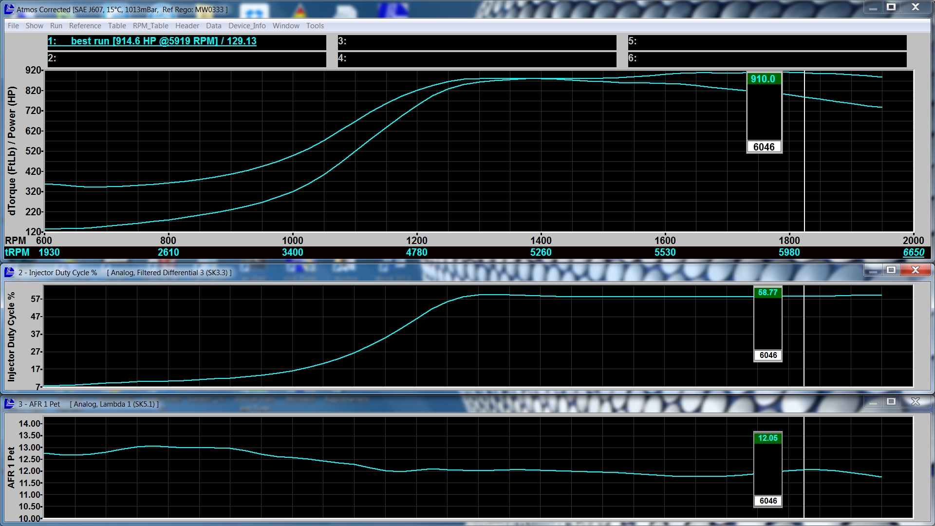
We will also show an example of Injector Duty Cycle and AFR, just to show the car was not running out of Injector:
So, Boost is all good, AFR is where tuner was happy with, happy days and off the car goes to customer….
But, on this car, as well as connecting Boost/AFR and IDC, we quickly “teed” in a Fuel Pressure Sensor at the Fuel Pressure Regulator to log Fuel Pressure. It could be said, for those without this option, you don’t need that, you can just have someone watch fuel pressure during a dyno pull. Two things come to mind here, you firstly need someone brave/stupid enough to have their head so close to an engine under full noise on a dyno, and then they have to be able to accurately recall what happened on an Analog Fuel Pressure gauge whilst all the noise and distractions were going on. Watching a Fuel Pressure Gauge buzzing around can be quite difficult in scenarios such as this.
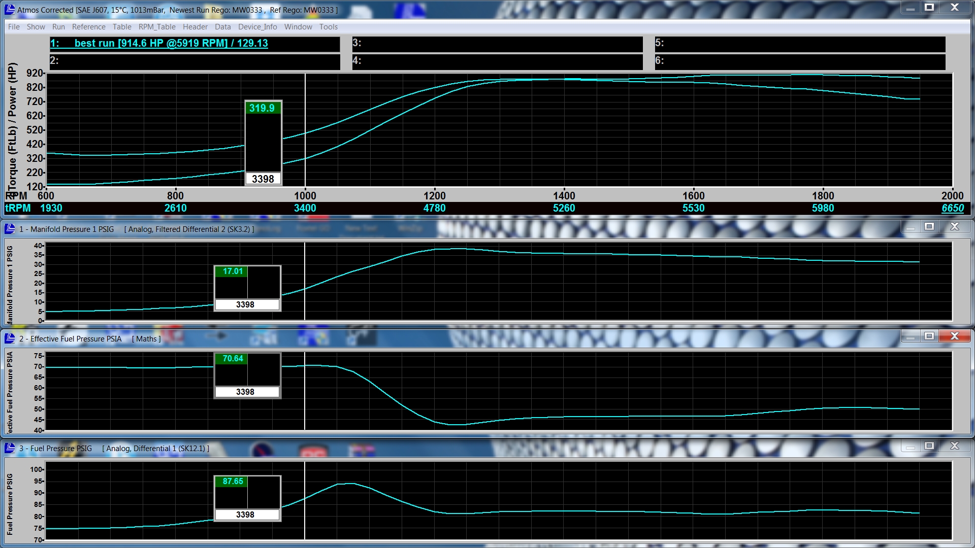
The below graph shows Boost and now Fuel Pressure. Notice how the Fuel Pressure heavily dipped once it got to around 94psi, dropping around 13-14psi:
Remembering this car, and most cars, have a 1:1 Fuel Pressure Regulator, this means that the Injector should see a constant Pressure Differential across it, so for Fuelling requirements, if the injector is opened for 5 Msecs, an accurate known quantity of fuel is Injected, regardless of Manifold Pressure.
Using a simple Maths Channel in the Mainline DynoLog Software, which in this case we have named “Effective Fuel Pressure”, and the maths involved are just Fuel Pressure minus Manifold Pressure. The below graph show this “Effective Fuel Pressure” Channel:
Notice how up until the car hit approx. 94psi Fuel Pressure the Effective Fuel Pressure was a pretty constant 70ish PSI, showing the Fuel Pressure regulator is doing its job as expected, and the Fuel system normal.
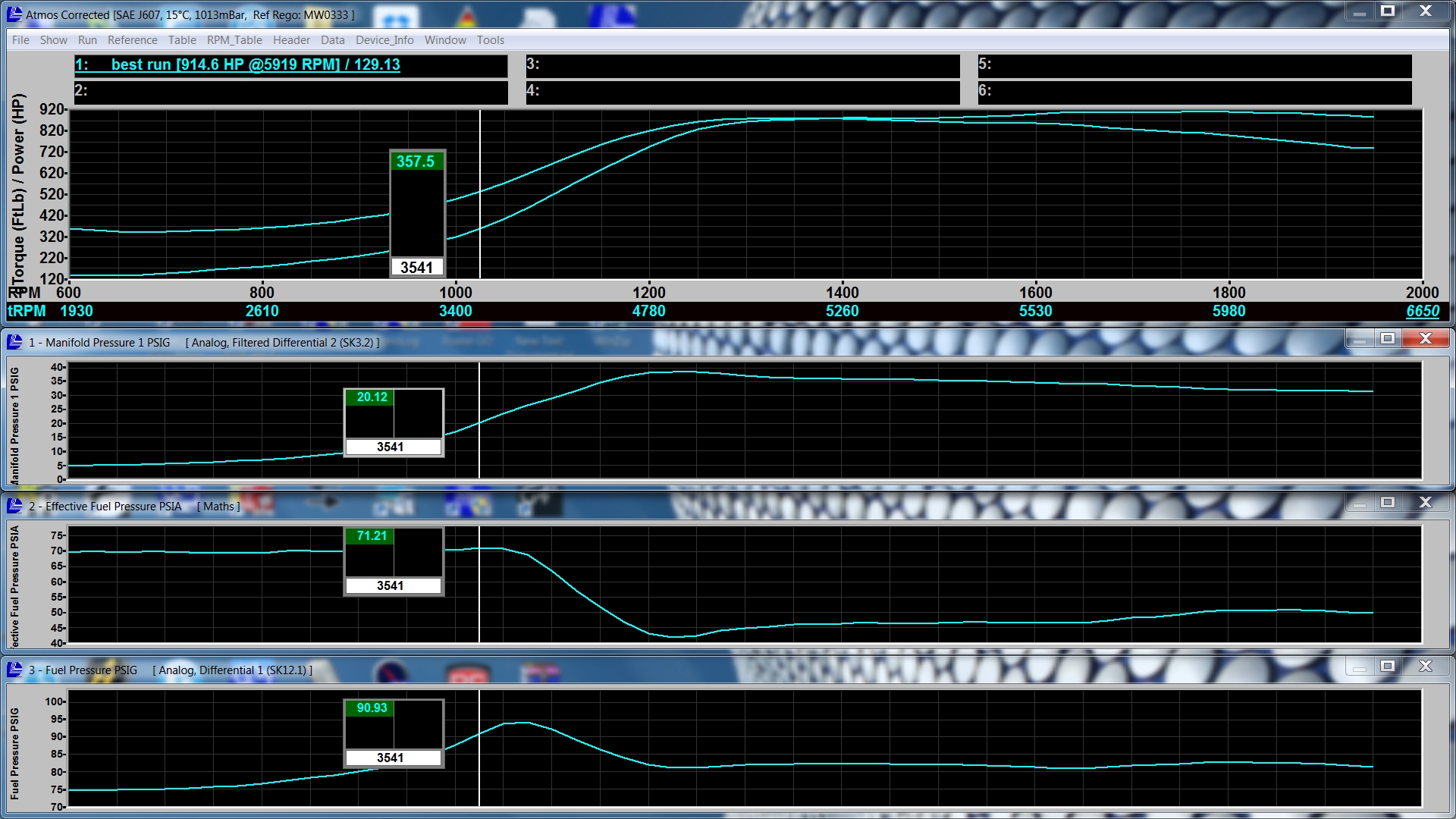
But, once at 94psi Fuel Pressure, the Effective Fuel Pressure plummets from 70psi to 42psi, a considerable drop, and would need a far greater than normal Pulse Width for a given Target AFR, as can be seen in the below graph:
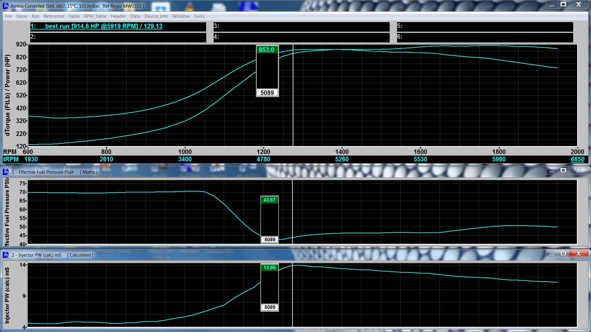
The measured Pulse Width is around 14m/sec max, whereas the required Pulse Width if the Effective Pressure was still 70psi, is around 9-10m/sec for a typical target AFR.
On a Mainline DynoLog Dyno the Injector Pulse Width is calculated from Injector Duty Cycle and Engine RPM.
The advantage of being able to log these parameters is a problem can be found well before the vehicle is handed back to the customer, and the workshop isn’t up for the cost of repairing a damaged engine due to a problem in the Fuel supply system.